
| Online Judge | Online Exercise | Online Teaching | Online Contests | Exercise Author |
|
F.A.Q Hand In Hand Online Acmers |
Best Coder beta VIP | STD Contests DIY | Web-DIY beta |
Series / Parallel Resistor Circuits
Time Limit: 2000/1000 MS (Java/Others) Memory Limit: 32768/32768 K (Java/Others)Total Submission(s): 187 Accepted Submission(s): 50
Problem Description
A series/parallel resistor circuit is shown here.
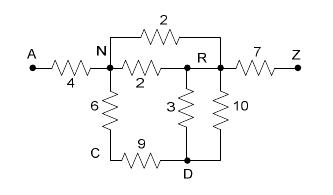
The resistance value is given next to each resistor. Connection points (wires connecting two or more resistors together, are denoted by an uppercase letter. A and Z are reserved for the names of the connection points which are the endpoints of the circuit. Our goal is to calculate the equivalent resistance of the circuit (i.e., the equivalent resistance between A and Z).
Within the circuit, a resistor can be specified by a triple consisting of the connection points at either endpoint, and the resistance. The resistor labelled ``9" could be specified as either (C, D, 9) or (D, C, 9). A circuit specification is the set of all resistor specifications.
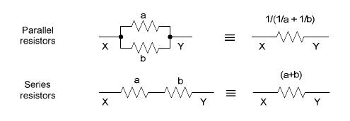
A pair of resistors is in series if one of either of their endpoints have a common connection point that is not use by any other resistor (e.g., the resistors labelled ``6" and ``9" are both connected to C, which is not connected to anything else). Two series resistors can be replaced by an equivalent single resistor whose resistance is the sum of the replaced resistors (15, in the previous example).
A pair of resistors is in parallel if both their endpoints have common connection points (e.g., the resistors labelled ``3" and ``10" above are both connected to R and D). Two parallel resistors can be replaced by an equivalent single resistor whose resistance is the inverse of the sum of the inverses of the two resistors ( (1/3 + 1/10)-1 = 2.307692 , in the previous example).
The equivalent resistance of a well-formed series-parallel resistor circuit can be determined by successively replacing a series or parallel resistor pair by the single equivalent resistor, until only one is left.
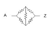
Not all circuits can be decomposed into series and parallel components. The Wheatstone Bridge, shown here, is a classic example of a circuit that is not considered a well-formed series-parallel resistor circuit.
The resistance value is given next to each resistor. Connection points (wires connecting two or more resistors together, are denoted by an uppercase letter. A and Z are reserved for the names of the connection points which are the endpoints of the circuit. Our goal is to calculate the equivalent resistance of the circuit (i.e., the equivalent resistance between A and Z).
Within the circuit, a resistor can be specified by a triple consisting of the connection points at either endpoint, and the resistance. The resistor labelled ``9" could be specified as either (C, D, 9) or (D, C, 9). A circuit specification is the set of all resistor specifications.
A pair of resistors is in series if one of either of their endpoints have a common connection point that is not use by any other resistor (e.g., the resistors labelled ``6" and ``9" are both connected to C, which is not connected to anything else). Two series resistors can be replaced by an equivalent single resistor whose resistance is the sum of the replaced resistors (15, in the previous example).
A pair of resistors is in parallel if both their endpoints have common connection points (e.g., the resistors labelled ``3" and ``10" above are both connected to R and D). Two parallel resistors can be replaced by an equivalent single resistor whose resistance is the inverse of the sum of the inverses of the two resistors ( (1/3 + 1/10)-1 = 2.307692 , in the previous example).
The equivalent resistance of a well-formed series-parallel resistor circuit can be determined by successively replacing a series or parallel resistor pair by the single equivalent resistor, until only one is left.
Not all circuits can be decomposed into series and parallel components. The Wheatstone Bridge, shown here, is a classic example of a circuit that is not considered a well-formed series-parallel resistor circuit.
Input
There will be multiple circuit specifications. The first input line for each circuit specification is an integer N (N < 1000 ), the number of resistors in the circuit. This is followed by N lines, each being a resistor specification in the form: X Y r , where X and Y are uppercase characters, and r is a positive integer resistance (r < 100 ). The equivalent resistance is guaranteed never to be greater than 100.
A circuit with N = 0 indicates the last circuit, and should not be processed.
A circuit with N = 0 indicates the last circuit, and should not be processed.
Output
For each circuit, if the circuit is well-formed and reduces to a single equivalent resistance between A and Z, print the equivalent resistance of the circuit from A to Z, rounded to (and displayed to) 3 decimal places. If the circuit is not well formed, or if there is no equivalent resistance between A and Z, simply print the number `-1.000'. There should be no blank lines between outputs.
Sample Input
8
N R 2
D R 3
R N 2
R D 10
Z R 7
C D 9
N C 6
A N 4
2
A Z 3
Z A 10
2
P A 6
P Z 9
5
A B 1
B Z 4
A C 8
C Z 19
B C 12
0
Sample Output
11.945
2.308
15.000
-1.000
Source
| Home | Top |
Hangzhou Dianzi University Online Judge 3.0 Copyright © 2005-2024 HDU ACM Team. All Rights Reserved. Designer & Developer : Wang Rongtao LinLe GaoJie GanLu Total 0.000000(s) query 1, Server time : 2024-11-22 16:33:10, Gzip enabled |
Administration |