
| Online Judge | Online Exercise | Online Teaching | Online Contests | Exercise Author |
|
F.A.Q Hand In Hand Online Acmers |
Best Coder beta VIP | STD Contests DIY | Web-DIY beta |
Bridging signals
Time Limit: 5000/1000 MS (Java/Others) Memory Limit: 65536/32768 K (Java/Others)Total Submission(s): 5761 Accepted Submission(s): 3540
Problem Description
'Oh no, they've done it again', cries the chief designer at the Waferland chip factory. Once more the routing designers have screwed up completely, making the signals on the chip connecting the ports of two functional blocks cross each other all over the place. At this late stage of the process, it is too
expensive to redo the routing. Instead, the engineers have to bridge the signals, using the third dimension, so that no two signals cross. However, bridging is a complicated operation, and thus it is desirable to bridge as few signals as possible. The call for a computer program that finds the maximum number of signals which may be connected on the silicon surface without rossing each other, is imminent. Bearing in mind that there may be housands of signal ports at the boundary of a functional block, the problem asks quite a lot of the programmer. Are you up to the task?
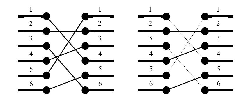
Figure 1. To the left: The two blocks' ports and their signal mapping (4,2,6,3,1,5). To the right: At most three signals may be routed on the silicon surface without crossing each other. The dashed signals must be bridged.
A typical situation is schematically depicted in figure 1. The ports of the two functional blocks are numbered from 1 to p, from top to bottom. The signal mapping is described by a permutation of the numbers 1 to p in the form of a list of p unique numbers in the range 1 to p, in which the i:th number pecifies which port on the right side should be connected to the i:th port on the left side.
Two signals cross if and only if the straight lines connecting the two ports of each pair do.
expensive to redo the routing. Instead, the engineers have to bridge the signals, using the third dimension, so that no two signals cross. However, bridging is a complicated operation, and thus it is desirable to bridge as few signals as possible. The call for a computer program that finds the maximum number of signals which may be connected on the silicon surface without rossing each other, is imminent. Bearing in mind that there may be housands of signal ports at the boundary of a functional block, the problem asks quite a lot of the programmer. Are you up to the task?
Figure 1. To the left: The two blocks' ports and their signal mapping (4,2,6,3,1,5). To the right: At most three signals may be routed on the silicon surface without crossing each other. The dashed signals must be bridged.
A typical situation is schematically depicted in figure 1. The ports of the two functional blocks are numbered from 1 to p, from top to bottom. The signal mapping is described by a permutation of the numbers 1 to p in the form of a list of p unique numbers in the range 1 to p, in which the i:th number pecifies which port on the right side should be connected to the i:th port on the left side.
Two signals cross if and only if the straight lines connecting the two ports of each pair do.
Input
On the first line of the input, there is a single positive integer n, telling the number of test scenarios to follow. Each test scenario begins with a line containing a single positive integer p<40000, the number of ports on the two functional blocks. Then follow p lines, describing the signal mapping: On the i:th line is the port number of the block on the right side which should be connected to the i:th port of the block on the left side.
Output
For each test scenario, output one line containing the maximum number of signals which may be routed on the silicon surface without crossing each other.
Sample Input
4
6
4
2
6
3
1
5
10
2
3
4
5
6
7
8
9
10
1
8
8
7
6
5
4
3
2
1
9
5
8
9
2
3
1
7
4
6
Sample Output
3
9
1
4
Source
| Home | Top |
Hangzhou Dianzi University Online Judge 3.0 Copyright © 2005-2025 HDU ACM Team. All Rights Reserved. Designer & Developer : Wang Rongtao LinLe GaoJie GanLu Total 0.000000(s) query 1, Server time : 2025-03-30 08:17:04, Gzip enabled |
Administration |